Determine Required Air Flow Using Calculations K. Im trying to get some help doing a rough estimate calculation of the volumetric flow through and induced draft fan on a balanced draft unit without doing a performance test.

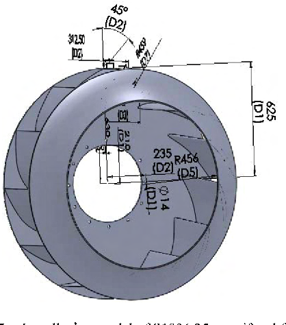
Figure 4 From A Digital Design Method Of Geometric Model For Centrifugal Fan Impeller Based On Solidworks And Vb Semantic Scholar
The importance of fan reliability often causes system designers to design fan systems conservatively.
. Effect of axial gap between inlet nozzle and impeller on efficiency and flow pattern in centrifugal fans numerical and experimental analysis. Sizing calculations of Boiler Pumps and ID FD Fans. Sheet Filename Title.
Let us first calculate. Performance Calculations 8 Fan Control 10 Fan Systems 11 Fan Selection Procedure 12 Process Data Sheet 15 APPENDIX A 16 APPENDIX B 18 APPENDIX C 20 APPENDIX D 22 APPENDIX E 25. Standard conditions are considered to be 70 degrees Fahrenheit with an elevation of zero feet sea level and an inlet pressure of zero inches of water column giving a density of 0075 pounds per.
In each case fan operation has a significant impact on plant production. - fan motor VFD driven operating amps. The sweet spot is when the inlet diameter of.
Depending on the number of blades designed for each fan the total impeller grid was approximately 3 to 4 million cells. Pneumatic conveying and other industrial process work Head Calculations 1 2 suction discharge For a fan Z 0. - fan inlet outlet pressures.
Simple in its design. 91 9302328890 9399948021 infomayafanin Facebook. No cooling system is needed due to small.
Typical ranges of fan efficiencies are given in Table 52. Motor power required for its working depends upon the following factors-ID Fan Capacity Quantity of flue gases drawn from the system measured in m3Hr. The online fan power calculation is to calculate the power required for fan to operate for the required airflow and pressure.
New Ideas for Future Research FD Fan Duct APH Duct Furnace Duct APH Back pass ESP ID Fan Chimney Duct Duct Analysis of Flue Gas at the ID Fan Inlet Partial pressure of each constituent in flue gas pCO2 16366209 kPa pO2 1138404 kPa PN2 68142138 kPa pSO2 0036081 kPa pH2O 13363218 kPa Mass flow rate of each constituent in tonshour. The ID fan problems have arisen from the bearing lubrication system which provides oil recirculation to the induction motor bearings and fan main shaft bearings. Fan efficiencies differ from design to design and also by types.
Coefficient 005 V K Q T-U S Sf 005 1200 10-5 242 2 108 m3min 381 CFM Determine Required Air Flow Using a Graph Search for the cross point A between output of heat Q. That being said you need to do some extra calculations with non-standard conditions as they can have a big impact on your fan sizing and design. Suitable for low pressure applications like domestic furnace medium size air conditioning units up to 25 tons 870Kw.
Let us assume Fan efficiency as 75 and Motor Efficiency as 90. PE 0 and Q 0 because fans are designed to overcome fluid friction. Fans fall into two general categories.
110000 lbhr at 950 PSI 905 F. It should be noted that final fan selection should be made by using Hudsons Tuf-Lite Fan Selection Program or by contacting Hudson Products. Approximate 250 mmWC Taking 20 margin on head ID Fan head 250 12 300 mm WC Power requirements of ID Fan.
The grid topology used for the impeller design calculation shown in Figure 5 was maintained. Feed Water inlet at 105 C and Exhaust gas temp at 150 C. Do not select fan in the pressure curve to the left of peak pressure.
Sample sizing calculations for BFW pumps and Fans for a typical Coal fired Boiler generating steam of 50000 Kghr at 67 kgcm2 and 485 degC. So from this performance calculation of ID fan a better design of a fan has been proposed to improve the plant efficiency and save the energy for global interest. Sizing calculations of Boiler Pumps and ID FD Fans.
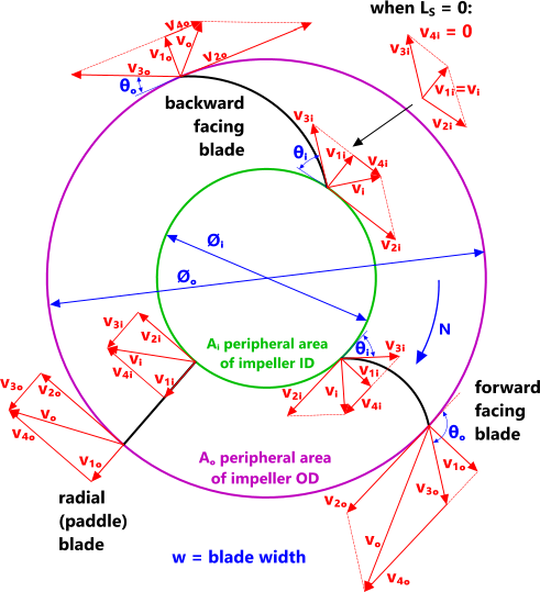
Concerned about being responsible for under-performing systems designers tend to compensate for uncertainties in the design process by adding capacity to fans. Books On Idfd Fan Design Calculations - posted in Industrial Professionals. Centrifugal flow and axial flow.
2008 IEEE Region 10 and the Third international Conference on. This projects aim is to analyse the ID fan lubrication system and then. Working range is from 40 to 70 of full range flow rate.
Power required for ID Fan BHP Flow x Head Efficiency x 758. KLM Technology Group Project Engineering Standard PROCESS DESIGN OF FANS AND BLOWERS PROJECT STANDARDS AND SPECIFICATIONS Page 2 of 26 Rev. Induced Draft ID Fan is used to draw the flue gases from the system generated from the combustion of fuel.
Fan total pressure FTP is the increase in total pressure pt measured by facing pitot tubes across the fan FTP pt2 pt1 101 Fan velocity pressure FVP is the average velocity pressure at the fan outlet only pv2 pt2 - ps2. Fan Laws and Fan HP Sizing Information from Fan Manufacturer Design Airflow CFM Design Static Pressure inches of WC Fan Speed Fan Motor Speed BHP Fan Power Fan Laws Table Airflow - CFM Static. Please do suggest on the same.
Fan Data RPM Motor Sheave Dia Fan Calculation authored and generated by CTC Design Inc. About Steam boiler steam and drawing thermodynamics steam table Know about some things Boiler Math solution Energy conservation thermodynamic therma. In centrifugal flow airflow changes direction twice - once when entering and.
ID Fan Motor Power Calculator. Calculations are provided for estimating fan power consumption and noise. ID Fan Design Calculations- Equations.
Consequently these issues have caused half-load unit 225 MW run-backs and full unit 450 MW trips over the past decade. - fan inlet temperature. Fan is unstable when overloaded.
ID Fan static Head Draft Loss in Boiler Duct Dust collector 150 50 50 mm WC. Here is the data that I have available to me in our historian. Online Induced Draft ID Fan Motor Power Calculator.
Axial And Centrifugal Fan Software Ciclo Software
2
Centrifugal Fan Design Calculations Xls Solution By Surferpix

Alumina Technology Ceti Enterprises Design Of F D Fan And I D Fan For Calciners In Alumina Refinery
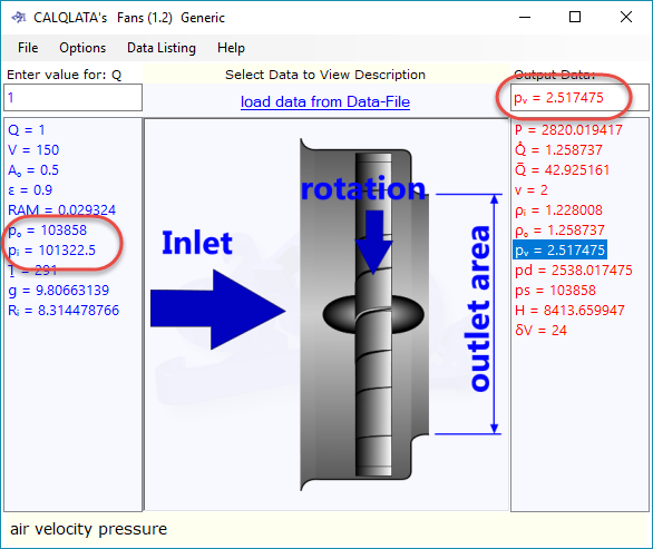
Fan Calculator Axial Centrifugal Pressure Flow Calqlata

Pdf Design Calculation Of Single Stage Radial Type Centrifugal Blower For Rice Mill Semantic Scholar
Fan Calculator Axial Centrifugal Pressure Flow Calqlata
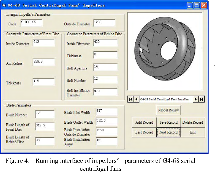
Figure 4 From A Digital Design Method Of Geometric Model For Centrifugal Fan Impeller Based On Solidworks And Vb Semantic Scholar
0 comments
Post a Comment